Go Back   Maxum Boat Owners Club - Forum > Maxum General > Projects and Customisations
Click Here to Login
Register FAQ Community Calendar Today's Posts Log in

Reply
 
Thread Tools Search this Thread Display Modes
 
Old 01-01-2011, 06:27 PM   #1
Lt. Commander

 
Join Date: Feb 2010
Location: Half Moon Bay, CA
Posts: 172
Default Garmin Radar project for 2600SE

I have a thread in the Sport Cruisers forum, but now that I've officially started a project I thought I'd move to here. I've sorted a few things out thanks to help from forum members. I've acquired a radar mount for the Garmin 24HD dome, and a new Nav light and mount. The components are in the attached picture.

Now I'm doing the planning for cable routing and wiring the nav light. I also have to figure out how to cap the aluminum cylinder that the old nav light was mounted on. I just need some sort of aluminum disk that I can drill a couple of holes in for screws.

The new nav light will be mounted using the wakeboard clamp you see in the picture. Not a perfect solution since it's kind of oversized, but it will attached to the tubing on the tower and then the light will mount to the flat part.

I'll post progress as it happens.

Click image for larger version

Name:	DSC07508.JPG
Views:	22
Size:	141.9 KB
ID:	1022
__________________

iceman is offline   Reply With Quote
Old 01-01-2011, 10:02 PM   #2
Admiral

 
seapuppy's Avatar
 
Join Date: Nov 2005
Location: Everett Wa
Posts: 4,681
Default

looks good however ....does the base plate cover the original holes??....if it does.....just fill the holes with white silicone sealant...then put the base plate over it...nobody will see it then....


or ..

take another picture of the holes for the anchor light..

SP
__________________

__________________
Don't compare your life to others. You have no idea what their journey is all about.
------------------------
SSN683 Association member
Par Excellence
------------------------------
2008 Bayliner 340 - "Wild Whim"
--------------------------------------
I live in my own little world....but it's okay-they know me here!!!

Avid practitioner of the martial art: KLIK-PAO.
Tap-Rack-Bang

Anyone that sez "Size doesn't matter" has never owned a boat!
seapuppy is offline   Reply With Quote
Old 01-02-2011, 08:00 PM   #3
Lt. Commander

 
Join Date: Feb 2010
Location: Half Moon Bay, CA
Posts: 172
Default

SP: The original holes for the nav light are at the top of a 4" high x 2" dia cylinder that will sit behind the radar dome (see photo). I'll remove the plastic nav light assy and cap off the cylinder. The 4" radar mount should raise the dome above the cylinder, but if not I have a shim plate. I'll mount the new nav light off to the side. I'm hoping I can drill a hole in the aluminum tower tube and pull the existing nav light power wires through to the new location.

Routing the radar network and power cables is going to be the biggest challenge. I think I'll run them along the outside of the tower tube because it would be pretty hard to fish them through the inside. At the bottom of the tower I'll cut a hole in the fiberglass bullkhead and run both cables in. The network cable will run forward to the helm and them come up through another hole to the display unit.

This is the first time I've tried to install something on the boat myself, so I'll be going slow so I don't screw up!
Attached Thumbnails
nav light.JPG  
iceman is offline   Reply With Quote
Old 01-02-2011, 10:54 PM   #4
Admiral

 
seapuppy's Avatar
 
Join Date: Nov 2005
Location: Everett Wa
Posts: 4,681
Default

ah....ok..that makes sense then...use black zip ties every 10-12" along the length of the al. pole your attaching it too.....also use some masking tape in the area of the fiberglass that way it will prevent drill bit walking.....and splintering of the gelcoat.....make sure you use plenty of 4200 silicone sealant at each entry to the fiberglass.....

keep those pictures comin!!!

SP
__________________
Don't compare your life to others. You have no idea what their journey is all about.
------------------------
SSN683 Association member
Par Excellence
------------------------------
2008 Bayliner 340 - "Wild Whim"
--------------------------------------
I live in my own little world....but it's okay-they know me here!!!

Avid practitioner of the martial art: KLIK-PAO.
Tap-Rack-Bang

Anyone that sez "Size doesn't matter" has never owned a boat!
seapuppy is offline   Reply With Quote
Old 01-03-2011, 08:21 PM   #5
Lt. Commander

 
Join Date: Feb 2010
Location: Half Moon Bay, CA
Posts: 172
Default

SP, thanks for the tips on working with fiberglass. I've been wondering about how to cut clean holes, and also how to keep the fiberglass edge from cutting the cables since I know fiberglass can be sharp. I guess some filing or sandpaper to smooth it out?

Also I'll need to cover the holes. There are stainless steel clamshell vents used in other places for other wires, so I'll try and look for those next time I'm at West Marine.
iceman is offline   Reply With Quote
Old 01-03-2011, 09:36 PM   #6
Admiral

 
seapuppy's Avatar
 
Join Date: Nov 2005
Location: Everett Wa
Posts: 4,681
Default

once you drill the hole...you do need to chamfer the holes so they don't splinter and crack...using a chamfer bit on the drill will work just fine...

then any holes that have wood backing....needs to be sealed with epoxy......seal the wood liberally......once you run the wires down thru the holes...then use 4200 silicon sealant and yes...clamshells work great to protect the entry.....

coil and stow any extra wiring and secure it safely so it doesn't chaff.......

SP
__________________
Don't compare your life to others. You have no idea what their journey is all about.
------------------------
SSN683 Association member
Par Excellence
------------------------------
2008 Bayliner 340 - "Wild Whim"
--------------------------------------
I live in my own little world....but it's okay-they know me here!!!

Avid practitioner of the martial art: KLIK-PAO.
Tap-Rack-Bang

Anyone that sez "Size doesn't matter" has never owned a boat!
seapuppy is offline   Reply With Quote
Old 01-14-2011, 08:54 PM   #7
Lt. Commander

 
Join Date: Feb 2010
Location: Half Moon Bay, CA
Posts: 172
Default progress

Finally making some progress. I removed the solar panel last week, and cut holes in the 1/4" aluminum panel on top of the tower for the mount and cables. It was harder than I thought to cut the big cable hole. Started with a drill, and then a dremel. It's ugly but it won't be visible and it will work. The excess cable will be stowed in the space between the aluminum mounting surface and the plastic panel mounted underneath.

I have a picture of the old nav light disassembled. I cut the wires and pulled them through an existing hole in the tower. Ultimately I'll use those for the new light.

I capped off the old nav light mount with an aluminum disk, sealed with 4200. There's a pic of that also.

The last pic is of the new light with the clamp on the tower tube. The mounting clamp is loose right now. It's a small gap so I guess I'll have to build it up with some kind of tape. The clamp holds it's position by friction with the tube so I'm a little worried it will slip over time.
Attached Thumbnails
alumplate5.jpg   capped.JPG   newlite.jpg   navlite.JPG  
iceman is offline   Reply With Quote
Old 01-21-2011, 02:36 AM   #8
Lt. Commander

 
Join Date: Feb 2010
Location: Half Moon Bay, CA
Posts: 172
Default Last weekend

A little late posting these, but here is some progress from last weekend. The 4" mount by itself didn't quite allow me to clear the nav light mount, so I had to use a 3/16" shim. It was a backing plate I ordered from the same manufacturer, and it worked perfectly. Second shot is the Radar dome on the mount, where you can see it does barely clear. Finally a shot showing the cables exiting the mounting plate at the bottom.

I did start to tie down the cables, and I drilled the hole in the fiberglass wall for the power cable, but I don't have pics of that yet.

Tasks for this weekend:
- seal the fiberglass entry hole per SP's instructions
- complete the cable runs and connect to 12 VDC power
- mount the new nav light and connect power
- power on radar and test

Click image for larger version

Name:	mount1.jpg
Views:	6
Size:	107.7 KB
ID:	1062Click image for larger version

Name:	dome on mount.jpg
Views:	11
Size:	92.0 KB
ID:	1063Click image for larger version

Name:	cabling.jpg
Views:	9
Size:	143.9 KB
ID:	1064
iceman is offline   Reply With Quote
Old 01-23-2011, 05:16 PM   #9
Lt. Commander

 
Join Date: Feb 2010
Location: Half Moon Bay, CA
Posts: 172
Default Success!

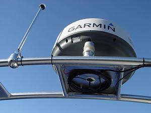
OK I'm done, not without a little drama at the end though. Everything went smoothly with the wiring of the new nav light, routing of the radar cables, and sealing the fiberglass entry hole. The attached pictures show the wires and cables underneath the mounting plate before and after being covered. I did have to build up the tower thickness with duct tape so the wakeboard clamp would hold securely. I hope that lasts longterm, otherwise I'll have to figure something else out.

So with all those cables secured above, I went down into the engine compartment to connect power to the dome. I found a bus strip that was installed for a floscan meter that had 12 VDC power brought back from the helm. This was nice because the power was switched by the ignition. I connected the dome to this power, and was ready for the first test. I turned on power to the boat and fired up the GPS plotter (Garmin 740S). It did not see the radar on the network. After trying a bunch of things to troubleshoot, I figured I'd have to call Garmin support and possibly send the dome back. But I had an inkling that maybe the power source wasn't adequate. I did measure the voltage going to the radar and it was OK (~13V) so I thought this was a longshot. Nonetheless I connected the dome to an external 12V power supply and sure enough, the GPS unit saw the radar and I was able to spin it up and see a display for the first time!

So at this point all I had to do was find a better source of power. That took awhile, but eventually I found a power strip that had the feed from the output of the DC main breaker. I jumpered this over to a spare terminal and connected the dome. This worked fine, so all I had to do then was strap down the cable in the engine compartment.

Not too bad an experience for my first installation on a boat, and at least I saved a few $$$!

Click image for larger version

Name:	wiring underneath.jpg
Views:	12
Size:	85.0 KB
ID:	1073Click image for larger version

Name:	covered.jpg
Views:	10
Size:	65.6 KB
ID:	1076Click image for larger version

Name:	finished1.jpg
Views:	15
Size:	200.8 KB
ID:	1075Click image for larger version

Name:	finished2.jpg
Views:	11
Size:	176.5 KB
ID:	1077
Attached Thumbnails
wiring complete.jpg  
iceman is offline   Reply With Quote
Old 01-23-2011, 10:53 PM   #10
Admiral

 
seapuppy's Avatar
 
Join Date: Nov 2005
Location: Everett Wa
Posts: 4,681
Default

Ice
well...it looks like you did an outstanding job on the install...but one question....how did you make the entry into the hull??....to me it looks like the wires are routed down the front of the arch...which it hinges on the fwd hinge???..do you hinge it on the fwd hinge or aft??


SP
__________________
Don't compare your life to others. You have no idea what their journey is all about.
------------------------
SSN683 Association member
Par Excellence
------------------------------
2008 Bayliner 340 - "Wild Whim"
--------------------------------------
I live in my own little world....but it's okay-they know me here!!!

Avid practitioner of the martial art: KLIK-PAO.
Tap-Rack-Bang

Anyone that sez "Size doesn't matter" has never owned a boat!
seapuppy is offline   Reply With Quote
Old 01-24-2011, 02:44 PM   #11
Lt. Commander

 
Join Date: Feb 2010
Location: Half Moon Bay, CA
Posts: 172
Default

Thanks SP. The wires are actually routed down the rear of the arch on the starboard side, down to the point where the tower pivots when lowering it. There was already a power cable there for the nav light and overhead arch lights. I added a hole there for the power cable to get to the engine room.

Funny thing is, I almost did route the cables down the forward part of the arch, because then I could enter the hull closer to the helm. But luckily I realized that would make it pretty tough to lower the arch!
__________________

iceman is offline   Reply With Quote
Reply


Posting Rules
You may not post new threads
You may not post replies
You may not post attachments
You may not edit your posts

BB code is On
Smilies are On
[IMG] code is On
HTML code is Off
Trackbacks are Off
Pingbacks are Off
Refbacks are Off


Powered by vBadvanced CMPS v3.2.3

All times are GMT. The time now is 11:31 PM.


Powered by vBulletin® Version 3.8.8 Beta 4
Copyright ©2000 - 2024, vBulletin Solutions, Inc.